Load Cell Fault Finding
We often get asked for fault finding tips and so I’ve put together a simple fault finding guide for a load cell system.
The output from a load cell is tiny! Any small interference will show up and then be amplified by the signal conditioner. The longer the cable the greater the interference will be due to increased coupling. It will be improved if screened, twisted pair cable is used as with a good quality signal conditioner this will allow a lot of noise to be removed.
A certain amount of physical noise is normal, especially in very sensitive load cells. This can be from all sorts of sources ranging from computer fans on the same desk as the load cell to fork lift trucks driving around on the floor above! The more sensitive your equipment, the greater the degree of separation that is required from the rest of the world!
In figure 1 below, we can see a diagram of a load cell system.
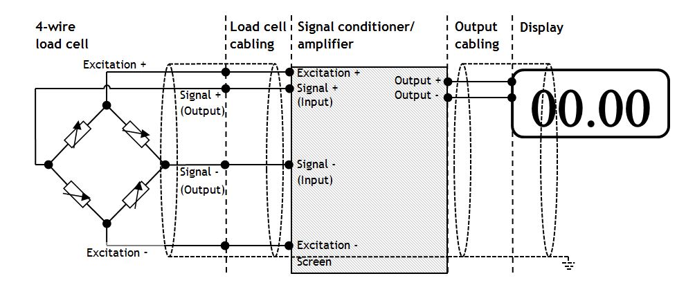
Figure 1. A load cell system
For this guide I have decided to split the fault finding into the areas load cell, signal conditioner and cabling.
I’ll start with the load cell…
Check correct wiring connections and colour coding
The first thing that I’d check is the wiring connections between the load cell and the signal conditioner. The colour codes vary between manufacturer and it is best not to assume anything. Usually the colour coding is on the load cell’s calibration certificate. Ensure that the wiring is as described. Getting this wrong can give inverted or biased results.
Check load cell resistance between excitation +/- and signal +/-
Also on the calibration cert should be the resistance between excitation +/- and also between the signal +/-. Measure those resistances with a multi meter to confirm that there is no internal damage to the sensor. (There will be a little variation from the figures stated on the calibration and this is normal). Don’t forget to disconnect the load cell from the signal conditioner before doing this.
Check for mechanical restriction on load cell movement
Have a good look at the load cell. Is it free to move? Any mechanical restriction will have an effect on the load cell’s output. (You can also use this phenomenon to limit the total movement of the loadcell to prevent accidental overload). Even poor cable routing can twist a small load cell and give skewed readings. Therefore it is important to make sure that the cable routing is free from any strain. Also the weighing vessel needs to be free to move in the direction of the load.
Check to see if load cell has been overloaded
Another possible problem is if the load cell has been overloaded. A small load cell could have been overloaded simply by leaning on it. If this has happened it may have permanently deformed the load cell and it will not return to its zero position correctly. This is likely to show as a non-zero reading under no load. There is a high chance that this will be terminal! Talk to your load cell manufacturer for more information.
Now we can look at the load cell cabling. As previously mentioned, the voltage outputs from the load cell are very small and easily influenced by the outside environment. There are several ways of minimizing the disruption.
Keep distance between load cell and signal conditioner to a minimum
The further apart the load cell and signal conditioner are, the more susceptible the cabling is to capacities coupling and electromagnetic fields. Keep this cable short and there will be less interference.
Keep all sensor cable runs away from inductive loads
It is very good practice to ensure that all sensor related cables including sensor power are kept separate from any inductive loads and their power feeds.
Ensure that you are using twisted pair, screened cable
Using twisted pair cable can help reduce the magnetic influence of power cables. This needs to be in partnership with a signal conditioner’s common mode rejection capability. Screened cable prevents capacitive coupling by coupling to ground instead of the signal wires.
Check cable is screened and only connected to ground at one point
If the screen is grounded at more than one point a ground loop is created. This is the cause of the earth hum in audio systems. This is just as problematic in instrumentation systems. Remove any extra link(s) between screen and earth. DO NOT disconnect the earth wire of the appliance in question. This is dangerous and can cause serious injury.
Test cable continuity
A simple continuity test can check the integrity of the cabling. Disconnect the cable and check the resistance.
Load Cell Fault Finding – Part 2
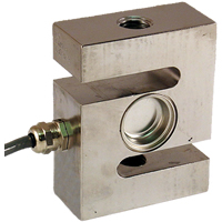
‘S’ Beam Load Cell
We already discussed the load cell part of the system, in this part we discuss the signal conditioning part of the system and provide a summary….
Check signal conditioner excitation voltage
If we measure the excitation voltage without the load cell connected we can check that it is the correct value for our load cell. A lower excitation voltage will give a smaller full scale reading but should still work correctly. A higher excitation voltage could cause the load cell to overheat and alter its characteristics. (If we then measure the excitation with the load cell connected this could show up other potential issues).
Check there aren’t too many load cells connected
We should also ensure that there are not too many load cells connected. Check the total resistance of the load cells either by calculation or measuring with a multimeter. Four 350 O load cells in parallel will drop the resistance to about 85 O. Check the specification on your signal conditioner to see what the minimum load is.
Short between signal inputs to signal conditioner to simulate zero load
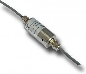
Mantracourt’s Signal Conditioner ‘ALA5′
The next check on the list is to short between the inputs on the signal conditioner. This will simulate a load of zero and should give a zero output (with gain and offset set to one and zero respectively).
Ensure that shunt cal is not active
Some signal conditioners have a shunt cal function. This shunts the output by a fixed value to check the integrity of the load cell, wiring and signal conditioner. If there is any deviation from the last time shunt cal was performed then further investigation is required. If shunt cal is left on then it will completely mess up any real readings. Please note that the shunt cal should never be applied without the load cell connected.
Check six wire or four wire load cell and signal conditioner
If you have a 6-wire signal conditioner with a 4-wire load cell it is important that you link the sense and excitation terminals at the signal conditioner. Otherwise there will be no sense input and therefore no reference point for the signal conditioner. (If you have a 6-wire load cell with a 4-wire signal conditioner it is worth linking the sense and excitation as this will reduce the overall wire resistance).
Check correct power supply to signal conditioner
Check the output from the signal conditioner is what the display needs as its input. Some signal conditioners can output several different protocols which need to be set up correctly.
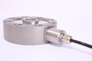
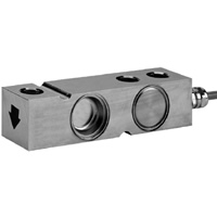
‘Pancake’ Load Cell
Ensure polarity is as required
Check that the positive direction of the load cell corresponds with the positive reading required.
Check gain and offset correctly set
Ensure that gain and offset are set correctly. It may be necessary to try recalibrating at this point if necessary, see the relevant manual. Depending on your setup this could be an absolute nightmare so should be held as a last resort.
The output cabling checks are very similar to the load cell cabling but will be marginally less prone to noise.
Most of the topics that I have covered here are very complex and I have barely scraped the surface. I’ve only very briefly touched on the output and display sections of the system which will be discussed in future blogs.
In Summary:
Check correct output type from signal
Check the signal conditioner has the correct power supply. See the relevant manual.
Load cell
- Check correct wiring connections and colour coding
- Check load cell resistance between excitation +/-
- Check load cell resistance between signal +/-
- Check for mechanical restriction on load cell movement
- Check to see if load cell has been overloaded
Cabling
- Keep distance between load cell and signal conditioner to a minimum
- Keep all sensor cable runs away from inductive loads
- Ensure that you are using twisted pair, screened cable
- Check cable is screened and only connected to ground at one point
- Test cable continuity
Signal conditioner
- Check signal conditioner excitation voltage
- Check there aren’t too many load cells connected
- Short between inputs to signal conditioner to simulate zero load
- Ensure that shunt cal is not active
- Check six wire or four wire load cell and signal conditioner
- Check correct power supply to signal conditioner
- Check correct output type from signal conditioner to display
- Ensure polarity is as required
- Check gain and offset correctly set
Hopefully this has given a helpful starting point for fault finding load cell systems.
Re-Published with permission of Mantracourt