
The GVSD 4001D is a high-precision digital single point load cell engineered specifically for low-capacity force measurement. Crafted from premium anodized aluminum, this sensor combines a compact, low-profile form factor with the robust performance required for demanding industrial and laboratory environments.
Whether you are integrating it into a medical device or a high-accuracy jewelry scale, the GVSD 4001D provides reliable data with minimal footprint. Its digital output ensures superior signal integrity compared to traditional analog sensors, reducing the risk of electromagnetic interference.
View or download the GVSD 4001D Anodized Aluminum Digital Single Point Load Cell datasheet below for full technical specifications and wiring diagrams.
Key Performance Specifications
Available in three precise weight capacities to suit your specific application:
- 200 grams (with overload protection engaged at 300g–325g)
- 500 grams (with overload protection engaged at 600g–625g)
- 1000 grams (with overload protection engaged at 1200g–1500g)
Advanced Features & Benefits
- Anodized Aluminum Construction: Provides excellent corrosion resistance and long-term durability while remaining lightweight.
- IP67 Environmental Protection: Sealed against dust and moisture, making it suitable for environments where washdown or high humidity is a factor.
- Low Profile Design: The ultra-slim form factor is ideal for integration into space-constrained machinery and portable weighing equipment.
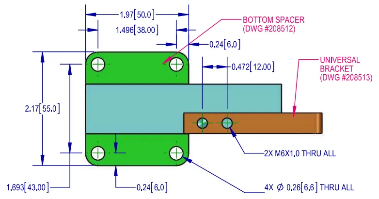
- Simplified Installation: Comes equipped with a special bracket and spacers, ensuring precise alignment and reducing setup time for engineers.
- Integrated Overload Protection: Built-in gaps protect the internal sensing elements from accidental damage during peak loads.
Versatile Industrial Applications
The GVSD 4001D is the go-to solution for industries requiring low-capacity force measurement. Common use cases include:
- Medical Equipment: High-accuracy diagnostic devices and fluid monitoring systems.
- Precision Weighing: Professional jewelry scales and laboratory balance systems.
- Automated Assembly: Force verification in delicate manufacturing processes.
- Robotics: Tactile feedback and light-pressure sensing.
Outline Dimensions
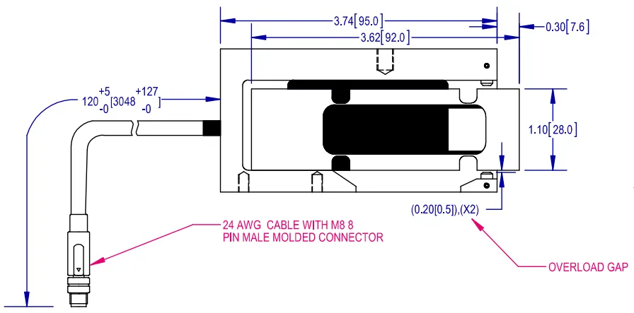
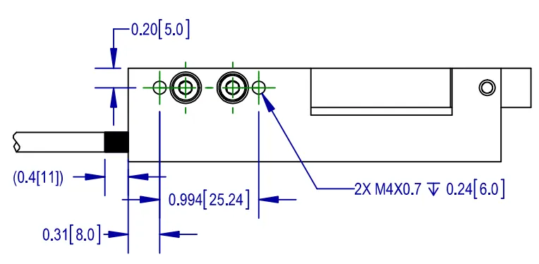
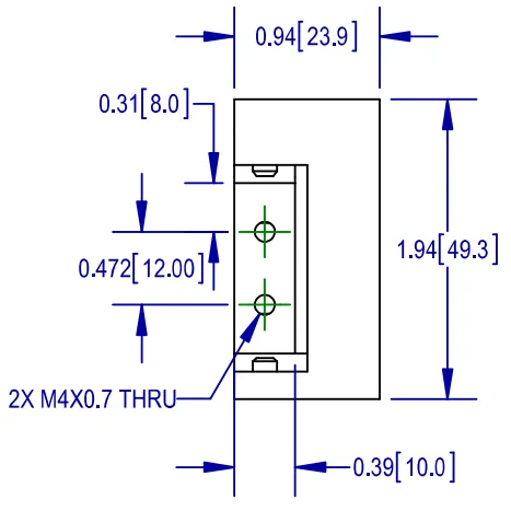
Load Cell Without Spacer and Universal Bracket

Load Cell With Spacer and Universal Bracket

Wiring
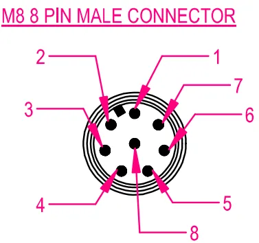
| Pin No | RS-232+CAN | RS-485+RS422 | Color Code |
|---|---|---|---|
| 1 | GND1 | GND1 | White |
| 2 | Program | Program | Brown |
| 3 | CANH | Rx+ | Green |
| 4 | Trigger Input | Trigger Input | Yellow |
| 5 | CANL | Rx- | Grey |
| 6 | RxD | Tx- | Pink |
| 7 | TxD | Tx+ | Blue |
| 8 | PWR+ | PWR+ | Red |
Specifications
| Model | GVSD | |||
|---|---|---|---|---|
| Capacity (E max) | g | 200 | 500 | 1000 |
| PERFORMANCES | ||||
| Combined Error | %FS | ±0.01 | ||
| Creep Error (30 min) | %FS | ±0.01 | ||
| Zero Balance, Raw Counts | Increments | See note 6 | ||
| Output resolution at full load, raw counts | Increments | 256000 | 512000 | 512000 |
| Internal AD conversion rate | upd./sec | 1200 | ||
| Fix, digital low pas IIR filter, default | Hz | 18 (Suppress 50Hz and 60 Hz influence) | ||
| Adjustable, digital low pass IIR filter Adjustable, digital low pass FIR filter | Hz | 18-0.25; selectable in 8 steps 40-5, selectable in 8 steps | ||
| Adjustable, external output update rate | upd./sec | 1200-9; selectable in 8 steps | ||
| GENERAL I/O’s | ||||
| Hardware interface, CAN version Hardware interface, RS version | CAN and RS232 RS485 and RS422 (both 4 wire) | |||
| Data transmission rate CAN Data transm, rates RS485/RS422/RS232 | kb | 125; 250; 500; 1000 9.6; 19.2; 38.4; 57.6; 115.2; 230.4; 460.8 | ||
| Protocol CAN Protocol RS485/RS422/RS232 | CANopen ASCII or Modbus RTU | |||
| Logical input, programmable | Trigger level 2-30Vdc, <3mA, Ref to Gnd | |||
| Power supply | VDC | +10 -+30<0.4 Watt | ||
| INFLUENCES | ||||
| Safe load limit | %FS | 150 | ||
| Ultimate load | %FS | 300 | ||
| Eccentric loading error acc. to OIML R76 | %FS | ±0.02 | ||
| Max platform size | mm | 200×200 | ||
| Temperature effect on zero | %FS/10°C | ±0.04 | ||
| Temperature effect on span | %FS/10°C | ±0.12 | ||
| Temperature range | °C | Operating: -10/+40 | ||
| EMC performance | MID Class E2 (industrial locations) | |||
| I/O protection, all pins | Reversed polarity; excess voltage and surge | |||
| Isolation body/electronics at 500VDC | G | >1 | ||
| Vibration | 2.5G operational; 5G non-operational | |||
| Environmental protection per IEC 529 | IP67 | |||
| Corrosion resistance | Anodized Aluminum | |||
Part Numbers
| Option | GEN | A | ||||
|---|---|---|---|---|---|---|
| Communication Interface | RS-232+CAN | RS-485+RS-422 | ||||
| Capacity (g) | 200 | 500 | 1000 | 200 | 500 | 1000 |
| G4 Part Number | 4001D-001-00 | 4001D-003-00 | 4001D-004-00 | 4001D-001-01 | 4001D-003-01 | 4001D-004-01 |
Notes:
- Shown loading direction is for positive output
- Refer 208504 control drawing for analog load cell manufacturing
- Overload gap is engaged at 300g-325g for 200g version
- Overload gap is engaged at 600g-625g for 500g version
- Overload gap is engaged at 1200g-1500g to 1000g version
- Zero balance, raw counts is within ±2000 and test after assembling universal bracket
and assembly box