
G4610
The G4610 is a full-featured multipurpose, easy-to-use digital strain gauge & load cell meter ideal for weight and force measurement applications.
View or download the datasheet below for full technical specifications and wiring diagrams.
Key Features
- 15, 30, 150, 300 mV Unipolar Input Ranges.
- ±15, ±25, ±150, ±250 mV Bipolar Input Ranges.
- Selectable 5 or 10 VDC Sensor Excitation.
- Supports up to twelve (12) 350 O Load Cells (Minimum Load Resistance of 28 O).
- Capture or Programmable Tare Feature.
- Auto-Zero Feature Eliminates Zero Drift.
- Ratiometric Operation.
- Max/Min or Peak/Valley Hold Feature.
- Large Dual-Line 6-Digit Display, 0.60″ & 0.46″.
- Dual-Scale Feature – Single Input.
- Rounding Function 1, 2, 5, 10, 20, 50, or 100.
- Programmable Display & Function Keys.
- 32-Point Linearization.
- NEMA 4X, IP65 Front.
- Input Power Options Include 85-265 VAC or 12/24 VDC.
- 2 or 4 Relays + Isolated 4-20 mA Output Options.
- External 4-Relay & Digital I/O Expansion Modules.
- USB, RS-232, & RS-485 Serial Communication Options.
- Modbus® RTU Communication Protocol Standard
- Configure, Monitor, and Datalog from a PC with Free MeterView® Pro Software.
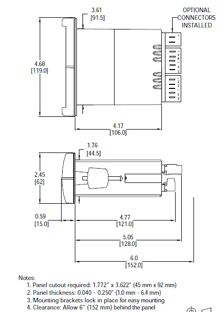
Outline Dimensions
ACCESSORIES
| Model | Description |
|---|---|
| PDA1002 | DIN Rail Mounting Kit for Two Expansion Modules |
| PDA1004 | 4-Relay Expansion Module |
| PDA1044 | 4 Digital Inputs & 4 Digital Outputs Module |
| PDA1200 | Meter Copy Cable |
| PDA1232 | RS-232 Serial Adapter |
| PDA1485 | RS-422/485 Serial Adapter |
| Model | Description |
|---|---|
| PDA7485-I | RS-232 to RS-422/485 Isolated Converter |
| PDA7485-N | RS-232 to RS-422/485 Non-Isolated Converter |
| PDA8008 | USB Serial Adapter |
| PDA8232-N | USB to RS-232 Non-Isolated Converter |
| PDA8485-I | USB to RS-422/485 Isolated Converter |
| PDA8485-N | USB to RS-422/485 Non-Isolated Converter |
| PDX6901 | Suppressor (snubber): 0.01 μF/470 Ω, 250 VAC |
Specifications
| Model | G4610 |
|---|---|
| General | |
| Display | Upper display: 0.60″ (15 mm) high. Lower display: 0.46″ (12 mm) high. Both are 6 digits (-99999 to 999999), red LEDs. |
| Display Intensity | Eight intensity levels |
| Display Update Rate | 5/second (200 ms) |
| Overrange | Display flashes 999999 |
| Underrange | Display flashes -99999 |
| Display Assignment | The displays may be assigned to PV1, PV2, PCT, max & min, set points, PV & units, units (lower display only), net & gross weight, Modbus input, and display millivolts |
| Units | lb, kg, ounce, gram, ton, metric ton (tonne), custom units. |
| Front Panel | NEMA 4X, IP65 |
| Programming Methods | Four front panel buttons, digital inputs, PC and MeterView Pro software, Modbus registers, or cloning using Copy function. |
| F4 Digital Input Contacts | 3.3 VDC on contact. Connect normally open contacts across F4 to COM. |
| F4 Digital Input Logic Levels | Logic High: 3 to 5 VDC, Logic Low: 0 to 1.25 VDC |
| Noise filter | Programmable from 2 to 199 (0 will disable filter) |
| Filter Bypass | Programmable from 0.1 to 99.9% of calibrated span |
| Rounding | Select 1, 2, 5, 10, 20, 50, or 100 (e.g. rounding = 10, value = 123.45, display = 123.50). |
| Recalibration | All ranges are calibrated at the factory. Recalibration is recommended at least every 12 months. |
| Max/Min Display | Max/min readings reached by the process are stored |
| Password | until reset by the user or until power to the meter is cycled |
| Non-Volatile Memory | All programmed settings are stored in nonvolatile memory for a minimum of ten years if power is lost. |
| Power Options | 85-265 VAC 50/60 Hz, 90-265 VDC, 20 W max, or jumper selectable 12/24 VDC ±10%, 15 W max. |
| Fuse | Required external fuse: UL Recognized, 5 A max, slow blow; up to 6 meters may share one 5 A fuse. |
| Isolated Transmitter Power Supply | Terminals P+ & P-: 10 VDC or 5 VDC ± 10%.12/24 VDC powered models selectable for 24 (should not be used for strain gauge/load cell), 10, or 5 VDC supply (internal jumper J4). (G4610): 85-265 VAC models rated @ 200 mA max, 12/24 VDC powered models rated @ 100 mA max, @ 50 mA max for 5 or 10 VDC supply. Note: Do not use 24 VDC to power strain gauge bridge |
| Greater than 60 dB at 50/60 Hz | |
| Isolation | 4 kV input/output-to-power line. 500 V input-to-output (powered by external supply). |
| Overvoltage Category | Installation Overvoltage Category II: Local level with smaller transient overvoltages than Installation Overvoltage Category III. |
| Overvoltage Category | PROVU Series (G4610): Operating temperature range: -40 to 65°C Storage temperature range: -40 to 85°C Relative humidity: 0 to 90% non-condensing |
| Environmental | PROVU Series (G4610): Operating temperature range: -40 to 65°C Storage temperature range: -40 to 85°C Relative humidity: 0 to 90% non-condensing |
| Connections | Removable screw terminal blocks accept 12 to 22 AWG wire, RJ45 for external relays, digital I/O, and serial communication adapters |
| Enclosure | 1/8 DIN, high impact plastic, UL 94V-0, color: black |
| Mounting | 1/8 DIN panel cutout required: 3.622″ x 1.772″ (92 mm x 45 mm). Two panel mounting bracket assemblies are provided |
| Tightening Torque | Screw terminal connectors: 5 lb-in (0.56 Nm) |
| Dimensions | 4.68″ x 2.45″ x 5.64″ (119 mm x 62 mm x 143 mm) (W x H x D) |
| Weight | 9.5 oz (269 g) |
| Warranty | 3 years |
| Strain Gauge Input | |
| Inputs | Field selectable: 0-15, 0-30, 0-150, 0-300 mV, ±15, ±25, ±150, ±250 mV, or Modbus PV (Slave) |
| Accuracy | ±0.03% of calibrated span ±1 count |
| Minimum Load Resistance | 28 Ω @ 5 V or 10 V |
| Maximum Excitation Current | 350 mA @ 5 V or 10 V |
| Temperature Drift | 0.002% of calibrated span/ºC max from 0 to 65ºC ambient, 0.005% of calibrated span/ºC max from -30 to 0ºC ambient |
| Function | Linear with multi-point linearization |
| Low-Flow Cutoff | 0-999999 (0 disables cutoff function) |
| Decimal Point | Up to five decimal places or none: d.ddddd, dd.dddd, ddd.ddd, dddd.dd, ddddd.d, or dddddd. |
| Calibration Range | Input Range Minimum Span Input 1 & Input 2 15 mV 0.2 mV 25 mV, 30 mV 0.4 mV 150 mV 2.0 mV 250 mV, 300 mV 4.0 mV An Error message will appear if the input 1 and input 2 signals are too close together. |
| Input Impedance | Voltage ranges: greater than 1 M Ω. |
| Relays | |
| Rating | 2 or 4 SPDT (Form C) internal and/or 4 SPST (Form A) external; rated 3 A @ 30 VDC and 125/250 VAC resistive load; 1/14 HP ( ≈ 50 watts) @ 125/250 VAC for inductive loads. |
| Noise Suppression | Noise suppression is recommended for each relay contact switching inductive loads. |
| Deadband | 0-100% of span, user programmable |
| High or Low Alarm | User may program any alarm for high or low trip point. Unused alarm LEDs and relays may be disabled (turned off). |
| Relay Operation | Automatic (non-latching), latching (requires manual acknowledge), sampling (based on time), pump alternation control (2 to 8 relays), Off (disable unused relays and enable interlock feature, manual on/off control mode). |
| Relay Reset | User selectable via front panel buttons or digital inputs. 1. Automatic reset only (non-latching), when input passes the reset point. 2. Automatic + manual reset at any time (non-latching). 3. Manual reset only, at any time (latching). 4. Manual reset only after alarm condition has cleared (latching). Note: Front panel button or digital input may be assigned to acknowledge relays programmed for manual reset. |
| Time Delay | 0 to 999.9 seconds, on & off relay time delays. Programmable and independent for each relay. |
| Fail-Safe Operation | Programmable and independent for each relay. Note: Relay coil is energized in non-alarm condition. In case of power failure, relay will go to alarm state. |
| Auto Initialization | When power is applied to the meter, relays will reflect the state of the input to the meter. |
| Serial Communications | |
| Protocol | Modbus® RTU |
| Slave ID | 1 – 247 (Meter address) |
| Baud Rate | 300 – 19,200 bps |
| Transmit Time Delay | Programmable between 0 and 199 ms or transmitter always on for RS-422 communication |
| Data | 8 bit (1 start bit, 1 or 2 stop bits) |
| Parity | Even, odd, or none with 1 or 2 stop bits |
| Byte-to-Byte Timeout | 0.01 – 2.54 seconds |
| Turn Around Delay | Less than 2 ms (fixed) |
| Isolated 4-20 mA Transmitter Output | |
| Output Source | Process variable (PV), max, min, set points 1-8, manual control setting, or Modbus input |
| Scaling Range | 1.000 to 23.000 mA for any display range |
| Calibration | Factory calibrated: 0.00 to 100.0 = 4-20 mA output |
| Analog Output Programming | 1.000 mA minimum and 23.000 mA maximum for all parameters: Overrange, underrange, max, min, and break |
| Accuracy | ± 0.1% of span ± 0.004 mA |
| Temperature Drift | 0.4 μA/°C max from 0 to 65°C ambient, 0.8 μA/°C max from -40 to 0°C ambient |
| Isolated Transmitter Power Supply | Note: Analog output drift is separate from input drift |
| External Loop Power Supply | 35 VDC maximum |
| Output Loop Resistance | Power supply Minimum Maximum 24 VDC 10 Ω 700 Ω 35 VDC (external) 100 Ω 1200 Ω |
| Digital I/O Expansion Module | |
| Channels | 4 digital inputs & 4 digital outputs per module |
| System | Up to 2 modules for a total of 8 inputs & 8 outputs |
| Digital Input Logic | High: 3 to 5 VDC Low: 0 to 1.25 VDC |
| Digital Output Logic | High: 3.1 to 3.3 VDC Low: 0 to 0.4 VDC |
| Source Current | 10 mA maximum |
| Sink Current | 1.5 mA minimum |
| +5 V Terminal | To be used as pull-up for digital inputs only. |
| 4-Relay Expansion Module | |
| Relays | Four Form A (SPST) rated 3 A @ 30 VDC and 125/250 VAC resistive load; 1/14 HP ( ≈ 50 watts) @ 125/250 VAC for inductive loads. |
Part Numbers
| Standard Models | SunBright Display Models | Options Installed | ||
|---|---|---|---|---|
| 85-265 VAC Model | 12/24 VDC Model | 85-265 VAC Model | 12/24 VDC Model | |
| G4610-6R0 | G4610-7R0 | G4610-6H0 | G4610-7H0 | None |
| G4610-6R2 | G4610-7R2 | G4610-6H2 | G4610-7H2 | 2 Relays |
| G4610-6R3 | G4610-7R3 | G4610-6H3 | G4610-7H3 | 4-20 mA Output |
| G4610-6R4 | G4610-7R4 | G4610-6H4 | G4610-7H4 | 4 Relays |
| G4610-6R5 | G4610-7R5 | G4610-6H5 | G4610-7H5 | 2 Relays & 4-20 mA Output |
| G4610-6R7 | G4610-7R7 | G4610-6H7 | G4610-7H7 | 4 Relays & 4-20 mA Output |