Connecting load cells to RS-485 – Guide overview
This quick setup guide provides a high-level overview of connecting load cells to RS-485 bus networks. It is intended to help users understand the basic network topology and initial connection concept.
This document does not cover the full command set or advanced configuration options. For detailed communication commands, parameters, and advanced features, please refer to the SPD Manual.
In addition, this guide demonstrates how to connect load cells to a PC using DOP4 software. It covers only the basic steps, functions, and windows required to connect up to four load cells in DOP4. Detailed instructions on DOP4 software features and advanced functions are available in the DOP4 User’s Manual
If you prefer to have a hard copy of these instructions or need to work offline at the installation site, you can download our Quick Setup Guide. This PDF document contains all the essential diagrams and condensed steps for connecting load cells to RS-485 networks in a convenient, portable format.
Download Connecting load cells to RS-485 guide
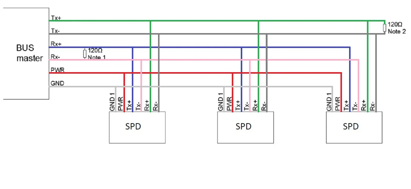
RS485 Wiring Diagram
Load cell color code & pin configuration
Wiring diagram for connecting load cells to RS-485 (four wire).
2-Wire Configuration
STANDARD PIN CONFIGURATION
| Pin No. | RS485 & RS422 | Color |
|---|---|---|
| 1 | GND1 | White |
| 2 | PROGRAM | Brown |
| 3 | Rx+ | Green |
| 4 | TRIGGER INPUT (IN0) | Yellow |
| 5 | Rx- | Gray |
| 6 | Tx- | Pink |
| 7 | Tx+ | Blue |
| 8 | PWR+ (+12 to 24 VDC) | Red |
| shell | Shield | Clear |
Connecting load cells to RS-485 – Setup Guideline
Before Connecting to the Bus
- Ensure that each load cell is assigned a unique sub-address.
(The factory-assigned load cell sub-address is indicated on the load cell label under the AD field.)
Communication Parameter Setup
- All load cells connected to the same RS485 bus must use the same baud rate.
- Load cells must be configured in Half-Duplex mode.
- Transmit delay should be configured based on trial results, typically 5–50 ms.
(This setting is especially important when communicating with a PLC or HMI.)
Note: The Streaming command is not available in Half-Duplex mode.
Configuration Using DOP4 Software
To view readings from all load cells simultaneously in DOP4:
- Establish working RS485 Serial connection between PC & load cell network
- Open DOP4 software
- Navigate to the Device selection window
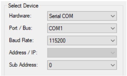
- Select the Hardware as Serial COM, Port, Baud rate, Sub address and set to channel and then Exit
- DOP4 Overview Window
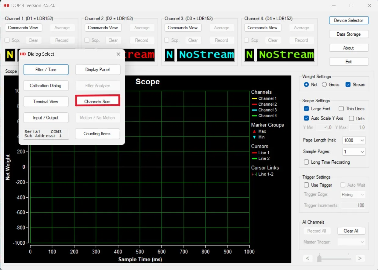
- Open the Connection Dialog window
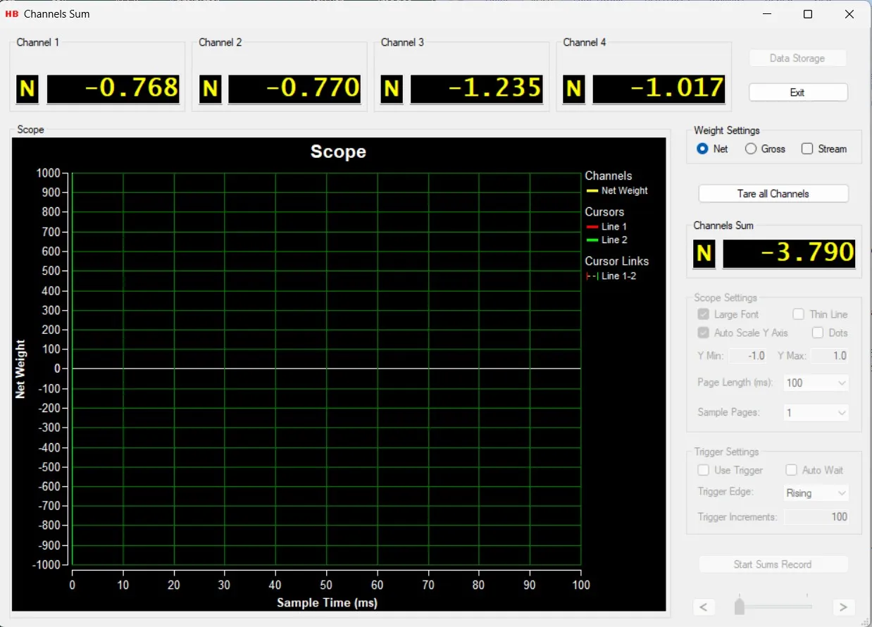
- Navigate to the Channel Sum window
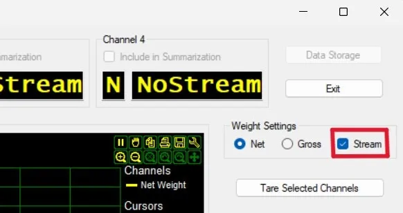
- Disable the Stream option
This configuration allows all load cell readings to be displayed simultaneously in the DOP4 software.
Device Selection
From the “Device Selector” dialog, Load cells to be used in DOP 4 software are selected.
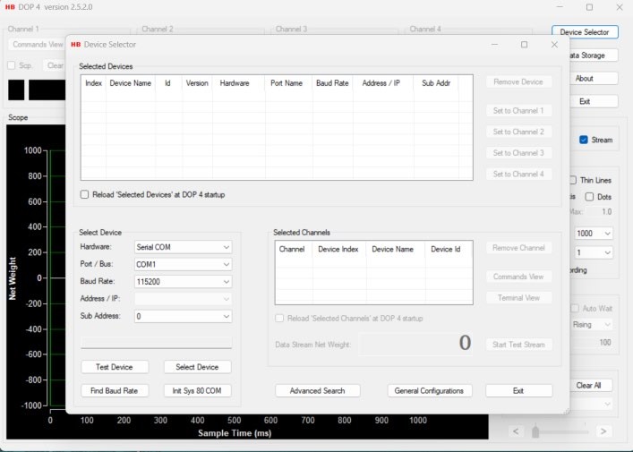
Select load cells and assign them to channels to be used in the main Window, calibration, and measurement dialogs. Up to 4 channels are available for assignment from up to four load cells.
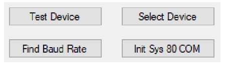
Functionality for testing cell connections, such as:
- Button “Test Device”: to use in case the COM port setup / speed is known.
- Button “Find Baud Rate”: to use in case the baud rate of COM port is unknown.
An Advanced Search dialog to search for connected devices by setting up different search criteria for different device interfaces are available.
A General Configurations dialog is available for setting up Tool Tips functionality and behaviors for the application in general.
Selecting & assigning G4 Digital load cell
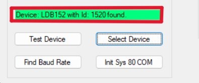
From the “Select Device” group box, select the Communication parameters for communicating with an Group Four Transducers load cell.
Select the G4 load cell by selecting the “Select Device” Button
If the load cell is found, the digital board name & ID will be displayed in the device status text field.
When checking the “Reload ‘Selected Devices’ at DOP 4 Startup” check box, the selected loadcell will be remembered for the next DOP 4 application startup. At next startup, just select a channel for the device if not already done and the “Device Selector” dialog can be exited.

From the “Selected Devices” group box, select one or more of the four “Set to” buttons.
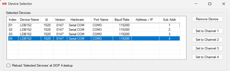
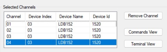
The selected load cell and the associated Channel can now be seen in the “Selected Channels” group box.
Select the “Exit” button to leave the “Device Selector dialog and enter the Main menu.
Main Overview Window in DOP4 Software
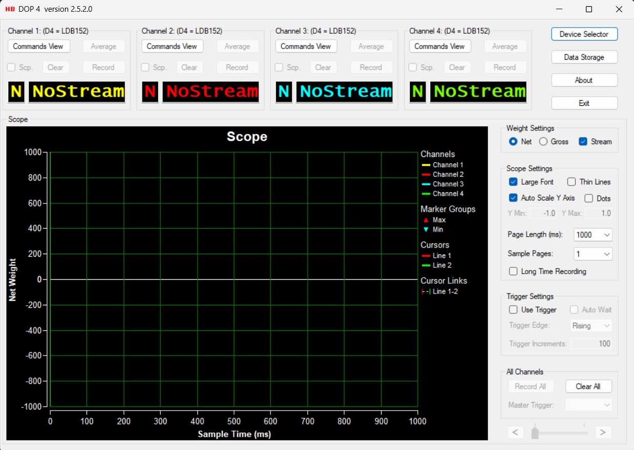
Navigate to the Channel Sum Window
Disable the Stream option
Annex
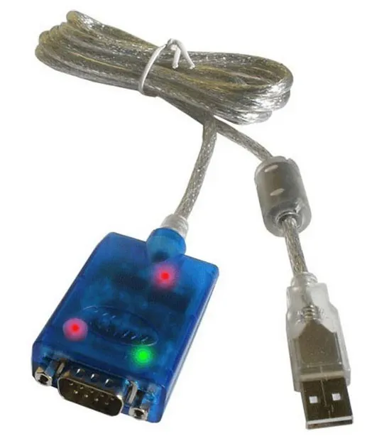
RS485 to USB converters
To establish a stable communication link between your PC and the measurement network, a high-quality hardware interface is required. When connecting load cells to RS-485 buses, most modern computers require a specialized converter to bridge the gap between the standard USB port and the industrial RS-485 serial interface.
Using a dedicated converter ensures reliable data transmission and protects your hardware from electrical noise. For the best results with the G4 series and DOP4 software, we recommend using the following industrial-grade solutions:
RS485/422 to USB converter cable. Group Four Transducers part number: 159.2-M12
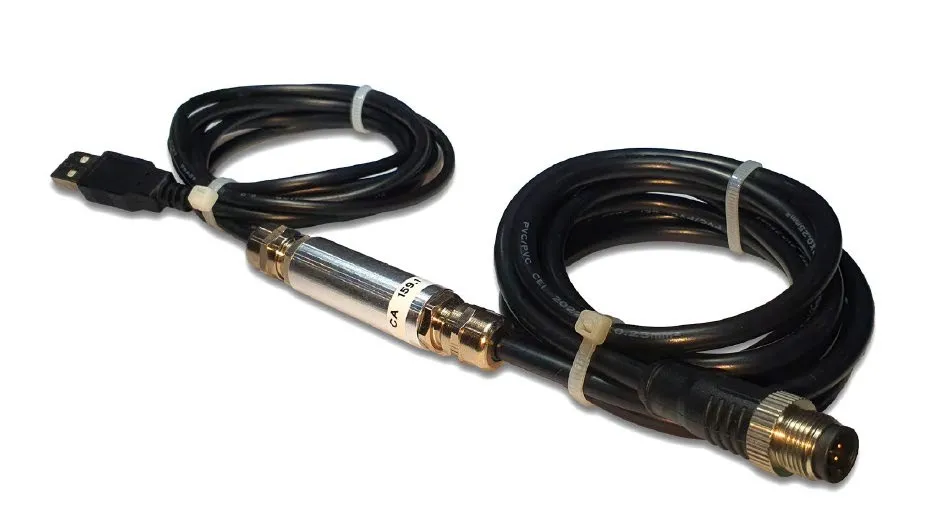
XS-890..
Link to the cable – USB to RS485 / RS422 Converter – PRO
This guide provided a step-by-step approach to connecting load cells to RS-485 using the G4 digital system and DOP4 software. By following these wiring and configuration steps, you ensure stable and accurate data transmission for your weighing system.
Frequently Asked Questions
What is the most critical step when connecting load cells to RS-485 networks?
The most important factor is ensuring that each device has a unique sub-address (AD field). Without this, connecting load cells to RS-485 will result in data collisions on the bus, making communication impossible.
I am having trouble with my DOP4 software setup. Why can’t I see my devices?
Most issues during DOP4 software setup are related to mismatched communication parameters. Ensure the Baud Rate and COM Port in the software match your hardware settings. If the device is still not found, use the “Find Baud Rate” tool within the Device Selector.
Does G4 load cell configuration require any special hardware?
Standard G4 load cell configuration is done via RS-485. However, to connect the bus to a PC for use with DOP4, you must use a high-quality RS-485 to USB converter. We recommend industrial-grade cables to ensure data integrity during configuration and measurement.
What are the advantages of 2-wire vs 4-wire RS-485 load cell wiring?
2-wire RS-485 load cell wiring is simpler and uses fewer conductors, which is ideal for Half-Duplex communication. 4-wire wiring (Full-Duplex) allows for simultaneous transmit and receive, but for most load cell networks, the 2-wire Half-Duplex setup is the standard and most cost-effective solution.
Why must I disable the “Stream” option in the Channel Sum window?
In a multi-drop network, streaming commands can cause bus congestion. When connecting load cells to RS-485 in Half-Duplex mode, disabling the stream ensures that the software polls each cell individually, allowing for a stable simultaneous display of all readings.